Contact
Home |240Z Mechanics| |Patents| |Art| |Recipes|
BioPatent Communications Contact Me for Discussions About Arts, Technology, and Culture (Blog Me/Pod Me).
| Rebuilding
an Engine
|
ContactHome |240Z Mechanics| |Patents| |Art| |Recipes| |
BioPatent Communications Contact Me for Discussions About Arts, Technology, and Culture (Blog Me/Pod Me). |
After about 200,000 miles, a 240Z usually requires an engine rebuild. Actually, most
of the major components such as the cylinder walls and main bearings will hardly be worn
and probably meet specifications. However, compression readings for cylinders may
become uneven and oil consumption past valve stem seals often begins. There may be
some embarrassing blue smoke off the line. Oil pressure may be almost nonexistent
idling on a hot day. Several times I have also experienced white (coolant) smoke
from a head crack or bad head gasket. The good news is these engines are
surprisingly easy and inexpensive to make young again.
This description of rebuilding a Datsun 240Z L24 engine focuses on the simple tasks of
replacing rings, seals and bearings in the block. While you are rebuilding the
block, the cylinder head should be taken to a machine shop for a professional rebuild or
at least you should replace the rubber valve stem seals.
The Datsun 240Z L24 engine is a relatively easy to pull, disassemble, inspect, repair and
install. A complete basic metric tool set plus a few specialty tools will allow you
to do most of the job yourself. An original Datsun shop manual (out of print) or a
good after market manual such as a Haynes manual is critical to successfully rebuilding
the L24.
Dissasembly.
Run diagnostic tests such as compression tests, coolant leak tests and combustion
chamber leak down tests before you destroy the evidence by tearing down the engine.
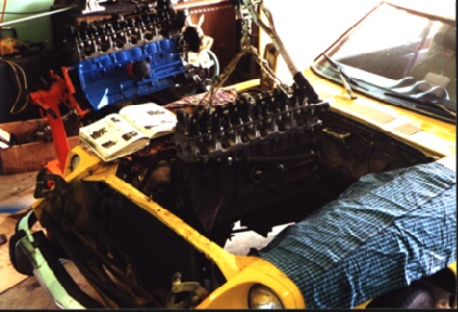
Clean the dirty grease off the outside of the engine before you start. This will
help keep disassembled parts clean and allow you to spray paint the block while it is out
of the engine compartment.
An engine rebuild is easy to start. Unhook all the hoses, linkages and wires between
the engine and car body. But wait! Have you ever seen a "basket
case" engine or motorcycle torn apart by some clod who forgot how to put it back
together? Use the shop manual. Place the screws, nuts and other parts into
labeled plastic sandwich bags as you go.
Make room in the engine compartment by removing the radiator, air filter housing and
exhaust pipe. Remove the alternator and starter motor. Support the
transmission on wood blocks, a dolly or transmission jack (things will go easier if your
transmission support has wheels). Remove the 4 bolts that hold the engine block and
transmission together. (Later, you can view the clutch components and consider
replacement of the clutch disk, throwout bearing and pressure plate. See my clutch replacement page.)
 Pulling the Engine. If you don't have a wheeled "cherry picker" to pull the engine,
attach a 2 ton "come along" (tool 1 below) hand wench to your garage rafters to
lift the engine. You should run an extra 4x4 along side one of the rafter beams for
a strong lift point. In 2-car garages, the span is greater so a strong 2x12 beam
should be mounted on end across the rafter beams. Extra metal braces should be added to
strengthen corners and joints. You don't want the triumphant moment of pulling the
engine spoiled as your ceiling falls in and the engine crashes back into your beautiful Z.
Pulling the Engine. If you don't have a wheeled "cherry picker" to pull the engine,
attach a 2 ton "come along" (tool 1 below) hand wench to your garage rafters to
lift the engine. You should run an extra 4x4 along side one of the rafter beams for
a strong lift point. In 2-car garages, the span is greater so a strong 2x12 beam
should be mounted on end across the rafter beams. Extra metal braces should be added to
strengthen corners and joints. You don't want the triumphant moment of pulling the
engine spoiled as your ceiling falls in and the engine crashes back into your beautiful Z.
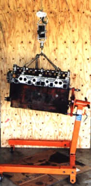
Remove the clutch pressure plate and fly wheel. With the engine suspended from the
rafters, it can easily be mounted to a movable engine stand ($50 and up). An engine
stand allows you move and pivot the engine around as you rebuild the block. Remove
the crank shaft pulley (a wheel puller is required), front case, cam gear and cam chain.
Mark the orientation of the cam gears and chain to simplify reassembly.
Remove the head bolts (10 mm Allen socket) and pull off the head.
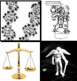
Inspection.
A quick visual inspection of the combustion chamber will tell you a lot about the
condition of the engine. Oil in a cylinder, from worn valve guides or piston rings,
will leave an oily black crust. Coolant entering a combustion chamber through a
blown head gasket or cracked head will leave it cleaned of the crusty deposits found in
the other combustion chambers. Burned valves, burnt pistons and thrown rods leave
deep scratches, obvious cracks and molten metal.
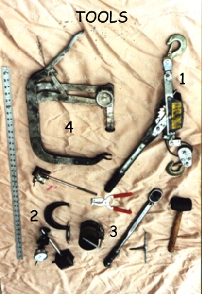 Inspection
for normal wear requires a set of several specialized
measuring devices. Check the block and head surfaces for flatness using a good
straight edge. A 1-inch micrometer is useful to check diameter, taper and roundness
of valve stems. A 2-inch micrometer is needed to measure crank journals (shaft
bearing surface) diameter. A 4-inch micrometer (tool 2 right) is used to measure
piston dimensions. A cylinder micrometer (tool 2 up) is slid into the cylinders to
check diameter, taper and roundness. With piston rings placed squarely in the
cylinders, piston ring gaps are checked with standard feeler gages. Rod bearing and
main bearing clearances can be checked with "Plastigages". Plastigages are
wax wires you place on a bearing surface before torquing the bearing cap in place.
When the bearing cap is removed, the Plastigage wax wires have been squished - tight
bearings squish them flat and wide, worn bearings barely flatten the plastigage.
The bearing clearance is read by comparing the squished Plastigage width to a supplied
chart.
Inspection
for normal wear requires a set of several specialized
measuring devices. Check the block and head surfaces for flatness using a good
straight edge. A 1-inch micrometer is useful to check diameter, taper and roundness
of valve stems. A 2-inch micrometer is needed to measure crank journals (shaft
bearing surface) diameter. A 4-inch micrometer (tool 2 right) is used to measure
piston dimensions. A cylinder micrometer (tool 2 up) is slid into the cylinders to
check diameter, taper and roundness. With piston rings placed squarely in the
cylinders, piston ring gaps are checked with standard feeler gages. Rod bearing and
main bearing clearances can be checked with "Plastigages". Plastigages are
wax wires you place on a bearing surface before torquing the bearing cap in place.
When the bearing cap is removed, the Plastigage wax wires have been squished - tight
bearings squish them flat and wide, worn bearings barely flatten the plastigage.
The bearing clearance is read by comparing the squished Plastigage width to a supplied
chart.
Check your shop manual for specifications of acceptable dimensions and clearances.
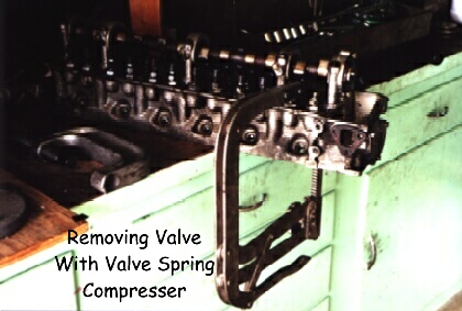
If the head is flat and valves not worn, it may not need machining by a professional shop
but the rubber valve stem seals should be replaced (see valve removal illustration
below). Piston rings and crankshaft bearings should be replaced since they are very
cheap and easy to install. If the engine "blew up" or is excessively worn,
the block should be brought to a machine shop for necessary repairs such as boring the
cylinders or turning the crank shaft on a lathe.
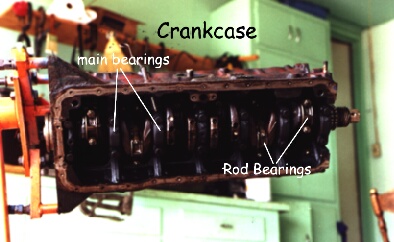
 Replacing Engine
Components. Rod bearings, main bearings, crank
shaft oil seals and piston rings are inexpensive. Replace all these parts even if
inspection finds all clearances within specification. Remove the rod bearing caps
and push the pistons out through the top of the block. Take care to observe the
orientation of all block parts so they can be replaced as they were (to help, many parts
are numbered by the manufacturer or have direction indicators).
Replacing Engine
Components. Rod bearings, main bearings, crank
shaft oil seals and piston rings are inexpensive. Replace all these parts even if
inspection finds all clearances within specification. Remove the rod bearing caps
and push the pistons out through the top of the block. Take care to observe the
orientation of all block parts so they can be replaced as they were (to help, many parts
are numbered by the manufacturer or have direction indicators).
Rod and main bearings are composed of two C-shaped half
sections. Finger pressure on the edge of an old rod bearing section is usually
enough to slip the rod bearing half section off a piston rod end or a rod bearing
cap. Old piston rings should be removed using ring pliers (tool 3 up). Unscrew
all main bearing bolts and pull off main bearing caps. Slip out main bearings as you
did with the rod bearings. The rear main bearing cap requires a special pulling tool
to remove. However, I have pulled them by pulling up on the crank with the overhead
"come along" while I tap on the rear main cap with a rubber mallet. With
all the rod and main bearings removed, the crank shaft can be removed for inspection and
for installation of a new rear main seal.
 Clean all parts
meticulously before installation of replacement bearings and rings. Prelubricate all
parts with engine oil plus STP before assembly.
Clean all parts
meticulously before installation of replacement bearings and rings. Prelubricate all
parts with engine oil plus STP before assembly.
Set all block-side main bearing halves in place, then set the crankshaft back in position
on top of them. Set the other main bearing halves in the main bearing caps.
Place the main bearing caps with their bearing halves over the crankshaft main journals to
complete the assembly of the block main bearings. Evenly tighten all the main bolts
to the point of contact before you torque them all to 15 ft-lb and finally to 38 ft-lb.
Use the piston ring pliers to put new rings on a piston, staggering the ring end gaps so
the first and second compression ring gaps do not line up. The 3-piece oil rings can
be carefully slid into the bottom piston ring groove by hand. Place a new rod
bearing half on the piston rod. With a piston ring compressor (tool 3 left), squeeze
the piston rings firmly into their grooves. Insert each rod and piston into the same
cylinder they originally came out of, and with the "F" mark on the piston facing
the front of the engine. With the ring compressor set fully flat to the block
surface and tightly squeezing the rings into their grooves, gently tap the piston into the
cylinder. Be sure the rod bearing sets into its crank shaft journal as the piston
slides into the cylinder. If the piston does not slide into the cylinder with gentle
tapping, do not force it - tap the piston ring compressor to ensure it is in flat contact
with the block and make sure the ring compressor is tight. Try again. Repeat this
process with the other five pistons and rods.
For each piston, set and lubricate a new rod bearing half
in a rod bearing cap. Assemble the rod bearings by placing the rod bearing caps over
the crankshaft rod journals and bolt them to the previously set rods. Tighten to
contact at first, then torque down to 10 ft-lb, then finally torque to 24 ft-lb.
Your block is rebuilt. You will have high compression and high oil pressure for at
least the next 100,000 miles.
Engine Reassembly. Reassemble in the reverse order of assembly. Modern head gaskets do
not require gasket cement. Before mating the head to the block, rotate the crank
shaft and cam shaft each to the cylinder #1 top dead center position (crank and cam
keyways pointing up). Otherwise, pistons and valves may clash as the head is placed
on the block. Starting from the center head bolts and working out, tighten all the
head bolts. Finger tighten, then torque all the bolts (starting again from the
center) to about 35 ft-lb and finally torque all the head bolts to 54 ft-lb. Install
the timing chain so the one silver link seats next to the mating mark on the crank gear.
Install the timing chain tensioner. Hold the timing chain taut to keep the
chain tensioner in place as the second silver chain link is seated next to the mating mark
on the cam gear (42 links between mating marks). The cam gear should now fit snugly
at the end of the cam shaft with the cam peg fitting into the number 1 hole of the cam
gear. Torque the camshaft gear bolt to 43 ft-lb.
Press a new front seal into the front cover. This can be done without a special tool
(but is easier with an inexpensive seal installation tool; essentially a properly sized
drift). Grease the seal inside and out. Place the front cover on a flat
surface, set the seal over the mounting hole with a flat board over it. Hold the
board level as you tap it with a mallet. The idea is to push the seal into the seal
mounting hole with even level force. Apply gasket cement to the scraped and cleaned
gasket surfaces of the block front and front cover. Install the front cover to the
block with gaskets in between.
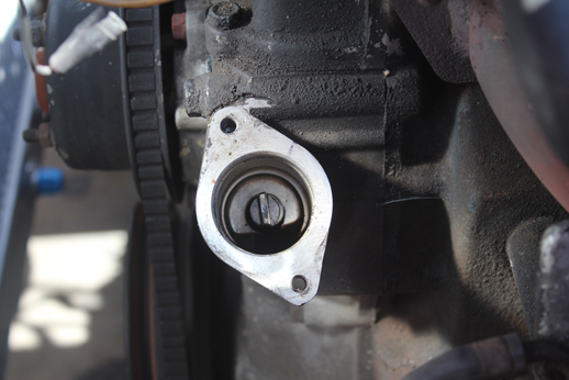 Set the engine to TDC piston 1. The oil pump should be replaced, preferably with a
high output pump upgrade. Install the oil pump/distributor driving spindle and then
the oil pump so the distributor end of the drive spindle can be seen (from above standing
on the driver's side of the block) in the distributor mounting hole with the end slot at
11:25 o'clock (not quite 12:00) and the smaller bow shaped projection facing front.
The spindle shifts about 15 degrees as it is meshes with the driving crank shaft worm gear
so repeat the oil pump installation until the distributor end of the spindle is oriented
as described above. This is critical to your ability to set the ignition timing
later.
Set the engine to TDC piston 1. The oil pump should be replaced, preferably with a
high output pump upgrade. Install the oil pump/distributor driving spindle and then
the oil pump so the distributor end of the drive spindle can be seen (from above standing
on the driver's side of the block) in the distributor mounting hole with the end slot at
11:25 o'clock (not quite 12:00) and the smaller bow shaped projection facing front.
The spindle shifts about 15 degrees as it is meshes with the driving crank shaft worm gear
so repeat the oil pump installation until the distributor end of the spindle is oriented
as described above. This is critical to your ability to set the ignition timing
later.
Replace the oil strainer and oil pan using new gaskets and gasket cement on clean
surfaces. Do not over tighten the oil pan bolts as this warps the seal surface
causing oil leaks. Install the water pump, manifold gasket, manifolds and
carburetors. Adjust the valve clearances cold to 0.007 inches intake and 0.010
inches exhaust.
Engine Replacement to the Engine
Compartment. Hoist the engine from the engine
stand with the over head "come along". Replace the flywheel being sure it
is well centered before gradually tightening the flywheel bolts to 100 ft-lb (for fun, you
figure out how to do this). Install the clutch disk (use a centering tool to align),
pressure plate and throw out bearing (all new parts is recommended). Lower the
rebuilt engine into the engine compartment. Support the engine on the mounting
brackets. Be aware that the left and right mounting brackets are not identical; the
passenger's side mount having more of an "elbow". As the engine is
lowered, it must also slide to engage the transmission spindle and align with the
transmission bell housing. (See tranny
installation page.) If it does not slide on easily, the clutch disk may not be
well centered. Use some extra long bolts, such as some head bolts, instead of the
regular transmission blots to initially align the block and bell housing. When the
transmission fits snug to the block, replace the extra long bolts with the regular
transmission bolts.
With your engine solidly in place, disengage the overhead support. Replace
components such as the distributor, fan, radiator, pollution control air pump, alternator
and starter motor. Reconnect the exhaust pipe, linkages, wiring and hoses.
Fill the engine with oil and the cooling system with
water. After about 500 miles of driving, replace the oil again.
BioPatent Communications Contact Me for Discussions About Arts, Technology, and Culture (Blog Me/Pod Me).
Return to BioPatent Home Page: Return to Home
|Protein Purification| |Patent and Trade Secret Page| |Lost Wax Casting Page|
|240Z Performance Modifications| |240Z Rejuvenation|
|Trademark Page| |Air-conditioning Repair|