BioPatent Communications
Addition of a Relay to a 240Z Starter System
The solenoid is part of the starter motor that receives the start signal voltage from the ignition switch. The solenoid is an electromagnet that pulls an iron rod core into itself when energized. The rod is connected to an electric switch that turns on the starter motor. The rod is also mechanically connected to a spring loaded lever to push the starter motor pinion gear into the ring gear of the fly wheel, thereby connecting the starter motor to the engine. When the ignition switch is released from "start", no electricity flows to the solenoid and the spring pulls the pinion gear back from the ring gear (preventing it from grinding when the engine starts). The solenoid does a lot of work and therefore demands a lot of voltage and current to work properly.
A common problem with 240Z ignitions is that not enough voltage is received by the starter solenoid to pull the lever, so the starter is not turned on and the pinion gear does not contact the fly wheel ring gear. Only a "click" can be heard as the solenoid jumps but fails to pull the lever all the way. This is because voltage through the ignition start circuit drops too much on the long trip from the battery through a small gage wire to the fuse block, across two buss fuse contacts, through thin wires to the ignition switch, across dirty and worn contacts in the ignition switch, and out a thin wire to the starter solenoid. Making matters worse, there is a huge drop in battery voltage when the starter motor tries to kick in. Several of the 240Zs I have owned experienced the problem of only clicking when the ignition switch is turned. It often took many clicks, sometimes leaving me wondering if the Z would start at all, before finally cranking the engine.
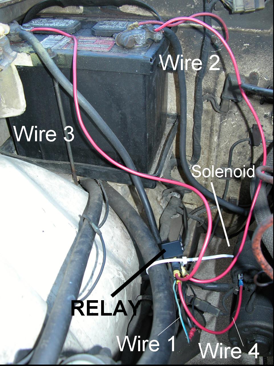
This article shows a way to provide a improved voltage and current to a starter solenoid for a reliable and strong start. Below is a picture showing an inelegant, but functional, arrangement of a relay circuit that vastly improved starting in my 1973 240Z. Please Note: Wire 3 should have a fuse in line.
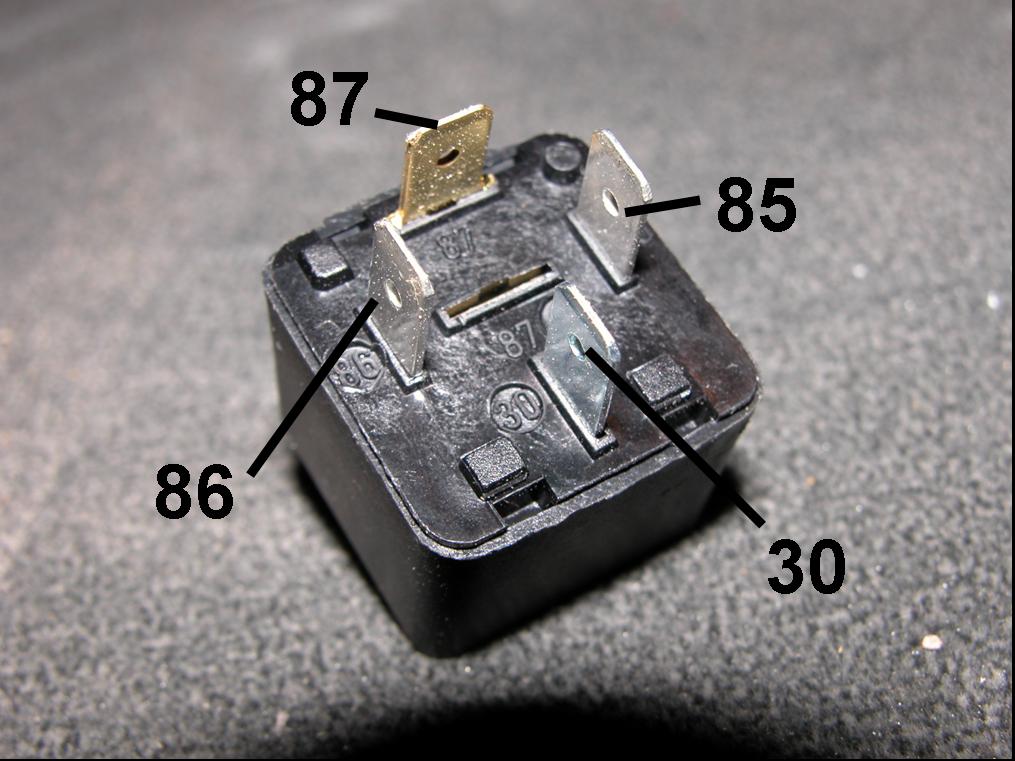
The relay system improves starting by providing full voltage directly from the battery instead of through the circuitous stock ignition circuit described above. I used a standard relay found in many modern cars and available at car parts stores or Radio Shack (30 amp model in the drawer of switches; ask the clerk if you can’t find it). The relays have 4 connections: the ignition switch wire and ground that control actuation of the relay, the power connection from the battery, and the output connection to the solenoid.
 To
set up a relay to your starter: run the ignition switch wire "1" (that normally
connects at the top of the solenoid) to connector 86 of the relay; run wire "2"
to ground from connector 85 of the relay; run a 12 gage wire "3" directly from
the battery positive terminal (through a 20 amp fuse) to connector 87 of the relay; and,
run a 12 gage wire "4" from connector 30 of the relay to where the ignition
switch wire originally connected to the top of the solenoid.
To
set up a relay to your starter: run the ignition switch wire "1" (that normally
connects at the top of the solenoid) to connector 86 of the relay; run wire "2"
to ground from connector 85 of the relay; run a 12 gage wire "3" directly from
the battery positive terminal (through a 20 amp fuse) to connector 87 of the relay; and,
run a 12 gage wire "4" from connector 30 of the relay to where the ignition
switch wire originally connected to the top of the solenoid.
1)
The ignition switch wire "1" connects to the female connector at the top of the
starter motor solenoid. You just have to
disconnect it from the solenoid and push it on to the connector p
2)
For the relay ground, I just make a 16 gage wire "2" with a female push on
connector at one end and a “ring terminal” connector at the other end. The push connector goes to the 85 terminal of the
relay and the ring connector is bolted or screwed to an available ground, such as, e.g.,
where the battery ground strap connects at the fire wall.
3)
A lot of current goes to actuate the solenoid, so I used a 12 gage wire "3" with
a ring terminal at the battery, a 20 amp fuse in line, and a female push connector to
connect at relay p
4)
Finally, a 12 gage wire "4" with female push connectors at each end is run
between the relay p
The setup shown was my test set and makes it easier to show where the wires go. The wiring can be organized better by mounting the relay to the engine compartment wall and running the wires carefully along the walls before jumping the wire "4" across to the solenoid connection on the starter. A nice alternative method to make connections to the relay is to use a standard relay socket to plug in the relay instead of making the connections with the 4 separate push connectors.
This same basic relay setup can be used with a signal coming from a horn switch or light switch to control horns and lights. This example web page is for education only and the writer is not responsible for attempts by readers to establish their own relay systems.
BioPatent Communications Contact Me for Discussions About Arts, Technology, and Culture (Blog Me/Pod Me).
Return to BioPatent Home: Return
Other BioPatent Pages:
|240Z Renewal Page| |Air-conditioning Repair|
|Performance 240Z| |Lost Wax Casting Page| |240Z Engine Rebuild| |Trademarks|