In this description of rear strut replacement, I installed Koni adjustable struts. The proper rear replacement struts were no longer available from Koni, so I made modifications of front struts to fit in the rear. Tokico has Premium Performance adjustable struts (Front: HZ3015, Rear: HZ3016) that I could have used without modification for somewhat more money.
For general comments on strut replacement, see the opening statements in the description of front strut replacement at Replacing Front Struts in a Datsun 240Z.
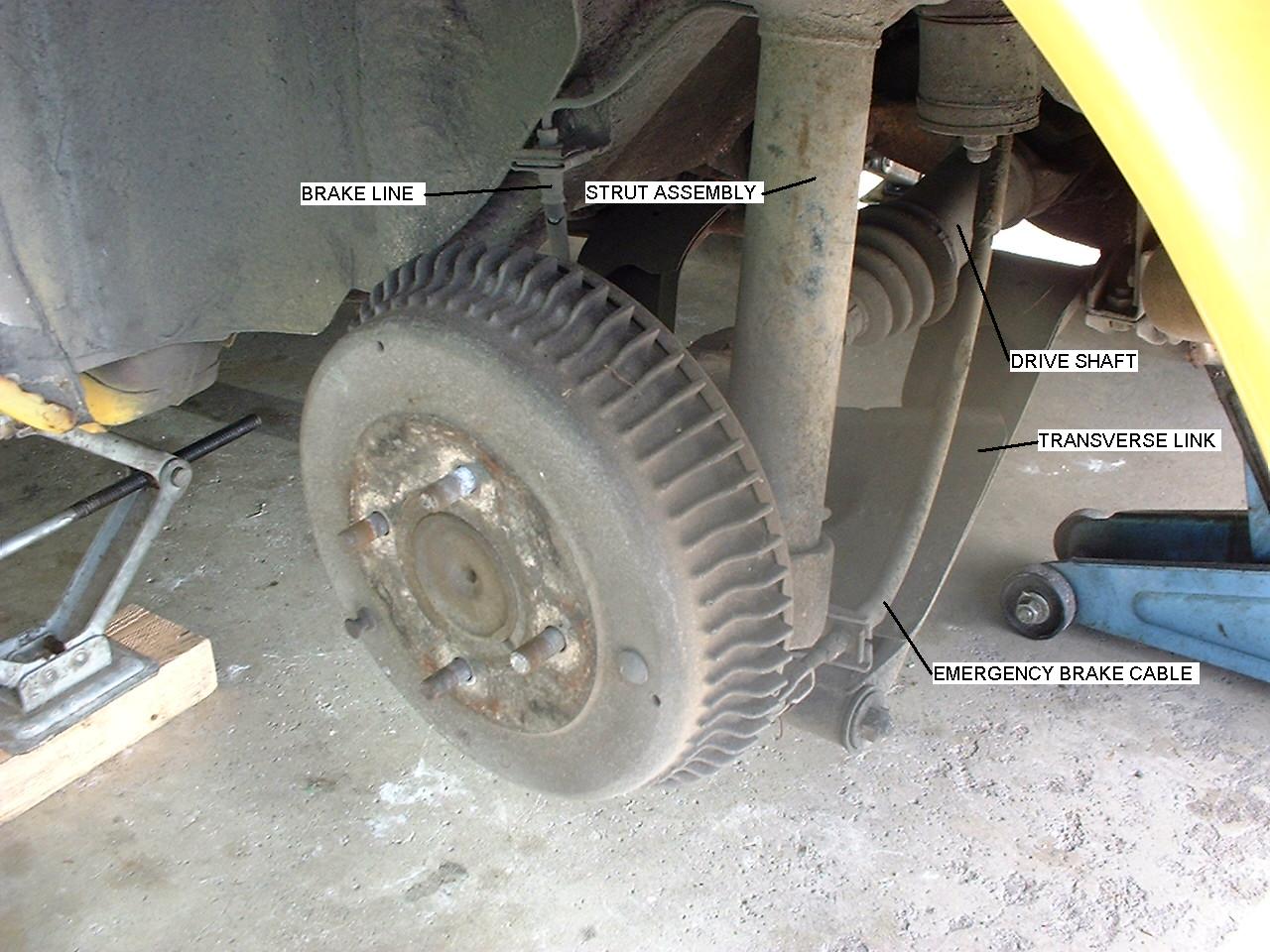
Rear struts can be removed in the order: 1) lift car, 2) remove wheel, 3) detach anti-sway bar (if present), 4) detach emergency brake cable, 5) detach brake line, 6) separate the drive shaft from the rear axel flange, 7) remove bolts from the inner rear transverse link bushing, 8) remove the center nut and bushing bolts from the front differential mount, 9) detach strut mounting insulator from the strut tower, 10) drop strut assembly with transverse link out from the wheel well, 11) compress the spring, 12) remove the self locking strut piston nut, 13) remove strut packing gland, 14) remove strut from strut assembly.
For an image showing some of these parts click Rear Suspension.
2. Go to Removing the Strut Assembly
Lift the Z Car. . It is a good idea to loosen the lug nuts on wheels before jacking up the car. Be safe. Use redundant supports. I lift the car with a good floor jack, set the unibody on jack stands, and fill the space under the tires with lumber. Grab the car and shake it to see how secure it is. Remove the wheel associated with the strut you are working on; keep the other wheels on for safety.
Removing the Strut Assembly from the Wheel Well. Detach the anti-sway bar (if present) from where it mounts to the transverse link (control arm). It can be connected with a typical connecting rod, rubber bushings and nuts. Some penetrating oil can be useful to help loosen the parts.
To disconnect the emergency brake cable, pull the cotter pin so the clevis pin can be removed allowing the clevis (cable attachment fixture) to be removed from the brake shoe pressing lever. The emergency brake cable can then be released by pulling off the mounting clip, and slipping the cable and spring out of the cable mounting fixture.
Separate the brake line where the solid line on the body attaches to the flexible line in the wheel well. Any time you work with brake lines in a 240Z you are in danger of striping the connectors unless you use a good (Sears Craftsman®) 10 mm tube wrench. I once ruined a brake line using a cheap tube wrench. These hydraulic brake connections commonly freeze up and are no fun to replace once destroyed. When the line has been disconnected, I use rubber vacuum hose plugs to stop brake fluid from leaking out onto the floor.
The drive shaft (half shaft) can be separated from the strut assembly by removing the 4 bolts holding the shaft to the rear axel companion flange. The splined shaft can be pushed off the flange.
It can be difficult to disassemble the transverse link spindle connection to the rear strut assembly. Instead, I find it easier to remove the transverse link from the inner bushing mounts. Remove the two differential mount bolts holding the front inner transverse link bushings. Loosen the remaining front differential mount nut and bolts. Remove the 2 bolts on the bracket holding the transverse link inner rear bushing. The 2 inner transverse link bushings can now be pulled out of their mounts to free the transverse link from the suspension mounts.
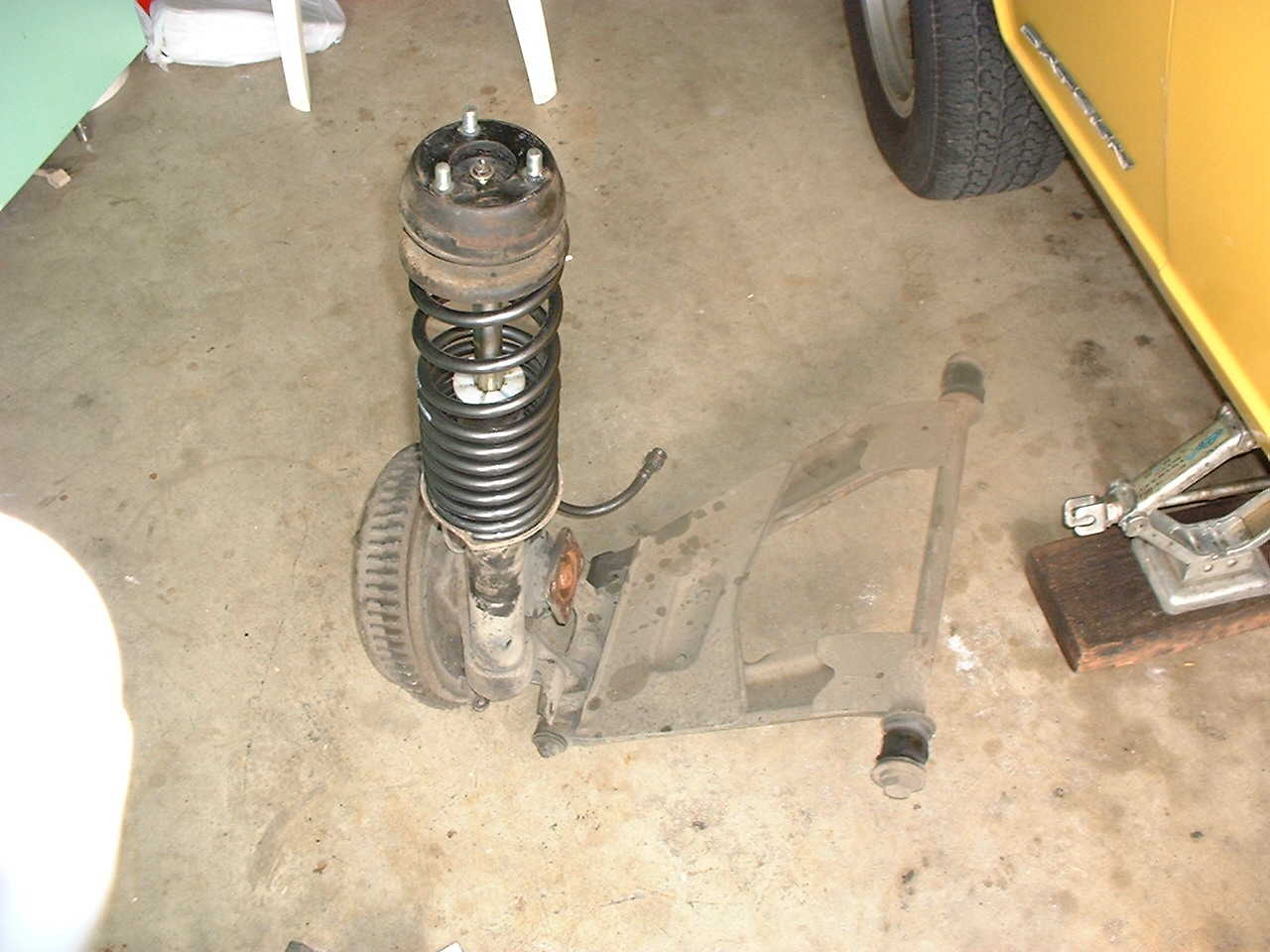
Detach the strut mounting insulator from the strut tower by removing the three mounting insulator nuts from the top of the strut tower (accessible from inside the rear hatch). Before removing the last nut, put a jack or some 2x4s under the strut assembly so it won’t fall when the strut assembly is released from the strut tower. The strut assembly can now be removed from the wheel well.
Removing the Strut from the Assembly. To remove the strut from the rear strut assembly, the spring must be compressed to take tension off the self locking strut piston nut. Inexpensive spring compressors come in pairs. I bought two pairs so I can use three compressors to compress one spring. If you only use two compressors, they tend to slide towards each other so the spring bulge dangerously to one side. The whole operation is more controlled and safe using three compressors. I use an air impact tool to drive the screws that compress the springs. This task is quite labor intensive and slow without air tools.
With the spring compressed, the self locking strut piston nut can safely be removed without the strut assembly exploding like a gigantic mouse trap. It takes a lot of force to remove the self locking strut piston nut, so the whole assembly has to be held firmly in a vice or with your foot holding a pry bar wedged into the assembly. Optionally, the nut can be removed without a firm hold on the assembly by using the sudden impact of an air impact tool. Observe the order and orientation of the parts (nut, strut mounting insulator, spacer, upper spring seat, spring, rubber boot) as they are removed from the assembly.
With the naked strut assembly in a pipe vise (or in a pipe wrench, with a wedged pry bar, or with the assembly still attached to the transverse link in the wheel well), the strut packing gland can be turned off the assembly with a pipe wrench. Sometimes this requires application of heat, application of penetrating oil, and/or striking the wrench with a mallet. With the packing gland removed, the old strut cartridge can slide easily from the strut assembly. On occasion, where the previous owner did not add cooling oil to the strut assembly before installation of the strut, I have had to rig a wench (come-along) to pull out the old strut.
Reassembly. Reassembly is the reverse of assembly. Use Never Seez on all threads so there will be less trouble the next time the parts need disassembly. Add half a cup (about 150 ml) of oil into the strut assembly to help transfer heat out of the strut while driving down the road. Insert the new strut into the strut assembly (My new strut was a shorter front strut, so a short piece of the old strut canister bottom end was cut off and dropped into the strut assembly to act as a spacer, ensuring a tight fit for the new strut.). Carefully tighten the packing gland (without cross threading) to about 45 ft-lb (about 6 kg-m); add a spacer at the top or bottom of the assembly if the strut remains loose when the gland is turned as far as it will go. Replace the associated strut assembly parts (rubber boot, spring, upper spring seat, spacer, strut mounting insulator, nut). Tighten the self locking strut piston nut to about 70 ft-lb (about 9 kg-m).
Reinstall the strut assembly into the wheel well. I usually ask an assistant to help guide the 3 insulating mount studs through the appropriate holes in the top of the strut tower while I lift the assembly. The assistant can quickly put a nut on a stud as soon as it comes through its hole. Replace the transverse link inner bushings in their mounts and bolt them in position. Attach the drive shaft to the axel flange with the 4 bolts; tighten to about 40 ft-lb (5 kg-m). Attach the brake line and emergency brake cable. Attach the anti-sway bar to the transverse link. Bleed the brakes and mount the wheels.
Return to BioPatent Home Page: Return to Home
|Protein Purification| |Patent and Trade Secret Page| |Lost Wax Casting Page|
|240Z Performance Modifications| |240Z Rejuvination|
|Trademark Page| |Air-conditioning Repair|